

Principle of Design of a Cellular Eye 1
The arguments just given do not mean that cellular eyes are impossible, but they must use principles other than geometric optics or intensity comparisons. In order to identify the geometric characteristics of a cellular eye, we will begin with principles and postulate that cells use the most optimal design. As mentioned earlier, an eye may be defined as an instrument that maps, in a one-to-one fashion, different directions toward an object space onto different points of an image space (see Fig. 5).

Fig. 5.
Generalized definition of an eye to achieve a one-to-one mapping of different directions in an object space onto different points in an image space.
If the different points of the object space (extra ocular space) are sources of a certain radiation, then the task of providing a one-to-one map of their direction can be formulated as the task of locating the direction of the sources. The general situation of an eye locating a source is illustrated in Fig. 6.

Fig. 6.
The most general design of a cellular eye to locate signal sources in its environment. The dotted lines indicate some of the directions of propagation of the signal toward signal receptors around the periphery of the eye. Even with an opaque interior (shaded area), the design does not yield a one-to-one mapping of source directions (object space) onto signal receptors (image space).
The object space is considered as a number of signal sources outside the cellular eye. Only one of them is depicted in Fig. 6. The ideal eye has to be rotationally symmetrical or it would be biased and prefer the detection of certain directions over others. It must contain receptors for the type of radiation that the sources emit (black dots in Fig. 6); these receptors must be spaced evenly to avoid directional bias. The receptors provide the points of the image space onto which the different directions of the signal sources are to be mapped. The design of Fig. 6. however, does not provide a one-to-one mapping because more than one receptor is exposed to the signals of the source. If the inside of the eye were transparent for the signal, the situation would be worse because every receptor would receive the signal. In order to minimize the ambiguity, we take the first step toward the final design of the cellular eye by filling the inside of the cellular eye with a material that is designed to absorb the signal (indicated by the gray area in Fig. 6).
Use of Blinds
Because optical methods fail to provide the one-to-one mapping between directions of signal sources and the set of receptors, the ambiguity of the signal reception must be reduced by other means. Perhaps the simplest and most effective block of the signals would be by blinds that are attached to one side of each receptor as indicated in Fig. 7.

Fig. 7.
Reduction of the ambiguity of the mapping function of the design shown in Fig. 6 by attaching blinds to the side of each receptor. The blinds are supposed to absorb the signal in their thickness. The improved design reduces the ambiguity, but does not eliminate it, because more than one receptor is exposed to the signal.
The blinds are supposed to absorb the signal by their thickness. Obviously, the use of the blinds reduces the ambiguity, although a one-to-one mapping is still not achieved. However, if we close the blinds in the manner shown in Fig. 8, only one receptor is exposed to the source, thus yielding the desired one-to-one mapping function. Optimally, the angle of the blinds is such that they extrapolate to the next receptor in the counterclockwise direction (see Fig. .
.

Fig. 8.
Final design of the geometry of a two-dimensional cellular eye. After closing the blinds in the depicted way, one and only one receptor is exposed to the signal source, insuring a one-to-one mapping.
If the angle is more radial, the ambiguity of Fig. 7 reappears. If it is more tangential, the design generates blind spots where signal sources cannot reach any of the receptors.
Three-Dimensional Shape of the Eye
The design as developed thus far works as long as the signal source remains within the plane of the ring of receptors. However, we must expect that the signal sources around the real cell are also located above and below this plane, as shown in Fig. 9.

Fig. 9.
Demonstration that the design of Fig. 8 is ineffective if the signal source moves out of the plane of the two-dimensional cellular eye. From the position of the source above the plane, all receptors are exposed to its signal, excluding a one-to-one mapping.
In this case, the full extent of the ambiguity of signal reception would reappear, since all receptors are exposed to the signal. Therefore, the next step in the construction of a cellular eye is the extension of the planar design of Fig. 8 into a three-dimensional one. Considering that the optimal design must remain rotationally symmetrical, there are only two possibilities for its spatial structure: a cylinder and a sphere. In the case of a sphere, it is apparent that it would not allow the attachment of blinds in a slanting fashion all over its surface. At least at the poles of the sphere the slanting directions would contradict each other. (This fact is known to mathematicians as the Theorem of the Well-Combed Hedgehog.) Therefore, the sphere has to be capped as shown in Fig. 10.

Fig. 10.
The only two possibilities for extending the two-dimensional cellular eye into the thirddimension are a straight cylinder or a capped sphere (a bulging cylinder).
In other words, the three-dimensional structure of the cellular eye has to be a straight or bulging cylinder, but a cylinder.
Requirement of Two Orthogonal Cylinders
The design as developed so far permits a one-to-one mapping between the set of signal receptors and the angle of the signal source as measured around the axis of the cylinder. Calling this angle the longitude of the signal source, it is obvious that we need to map its latitude as well if we wish to identify the direction of the signal source. Since the longitude and latitude of a point are angles measured around axes orthogonal to each other, the design requires a second cylinder at right angles to the first, as shown in Fig. 11.

Fig. 11.
Necessary use of a pair of orthogonally oriented cylinders as a cellular eye to determine simultaneously the longtitude and latitude of the signal source (see text).
Therefore, we conclude that the cellular eye would be a pair of cylinders at right angles to each other, each having the cross section shown in Fig. 8. It hardly needs mentioning that this design bears striking resemblance to a pair of centrioles. If the arguments as presented are correct, then the structure of centrioles and basal bodies is the expression of a physical necessity and not the result of an accident of evolution, which may explain the high degree of conservation of centriole structure throughout nature. The right-angle orientation can be expected to be found whenever the signal sources are distributed in three-dimensional space. If under special circumstances the relevant signal sources are distributed in a plane, only one cylinder is required that is oriented perpendicular to this plane. We speculate, therefore, that the array of basal bodies that are oriented perpendicular to the surface of a ciliated cell not only form nucleating structures for the cilia but also act as monitoring devices for signal sources at the cell surface.
Refinement of Angular Resolution
The similarities between a hypothetical cellular eye and the structure of centrioles and basal bodies extend even further if we try to optimize the angular resolution of the device. The design developed so far limits the angular resolution by the number of receptors and blinds around the perimeter of the cylinder. If a signal source is located anywhere in the sector defined by the angle between adjacent blinds, it will be detected by one and the same receptor. In other words, if the cross section of the cylinder has N blinds, then the limit of angular resolution is Θ = 360°'IN. Therefore, it would be desirable to improve the design in such a way that it can distinguish various directions in each sector. The most direct method to improve the angular resolution would be to increase the number of receptors and blades (N). However, each blade must have a certain thickness in order to absorb the signals. Therefore, the number N cannot be increased at will. A much more elegant way to achieve better angular resolution is to attach the blinds in such a way that they lean across one sector as they run from the top of
the cylinder to the bottom (see Fig. 12).
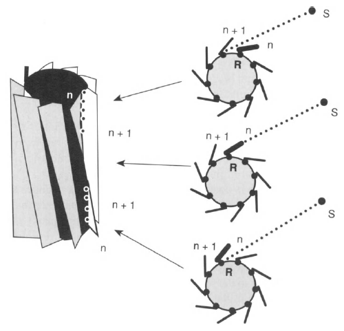
Fig. 12.
Pitch of the blades as a means to improve the angular resolution of the design. The percentage of receptors on blade n exposed to the signal source S is a measure of the location of the signal source in the sector between two adjacent blades (see text).
The blades of actual centrioles and basal bodies are, indeed, pitched in this way (cf. Fig. 1). Assume that the viewer is positioned at the location of the signal source S. As shown in the perspective drawing of Fig. 12, the viewer would see the outside of some blades (gray shading), the inside of other blades (white areas), the opaqueness of the inside of the cylinder (black areas), and the rows of receptors exposed to the direction of the source (dots lining the blades). The main difference from the earlier design is the exposure of some receptors along blade n and some receptors along blade w+1 to the source. Therefore, at first sight, the pitched blades may seem to defeat our initial intention of providing a one-to-one mapping between receptors and directions of signal sources. However, the exposed receptors on adjacent blades differ by their position along the blades. More importantly, the apparent ambiguity offers the possibility to determine the location of the direction of the signal source in the sector of blade n. By determining the ratio
number of receptors exposed on blade n
r = -------------------------------------------------
number of all receptors on blade n
(see Fig. 12), the angle φ of the signal source reaching receptors on blade «becomes φ = (n + r)6 This angle is no longer an integral multiple of the former limit of resolution Θ = 360°'/N, but contains fractions of Θ, thus improving the angular resolution. It is still limited, though, because of the finite number of receptors lining the inner edge of each blade. The explanation of the calculation just presented is obvious if one considers a
series of cross sections along the cylinder axis, as shown in Fig. 12. As we move up the axis, the cross sections rotate by the angle of one sector. Depending on the direction of the source within the sector, the blade will cut off the signal source at some distance from the bottom of the cylinder, giving rise to the ratio calculated.
Likely Wavelength of Signal Sources
The next important question about our speculation concerns the physical nature of the postulated signal sources. Considering that the function of the cellular eye is to locate objects (signal sources) in the environment of the cell, one may argue that the wavelength emitted by the sources must be linked to the size of these objects. If the objects were smaller than the wavelength, then the cellular eye would not be able to resolve two objects closer than the wavelength. It seems reasonable to assume that the interesting objects around probably include other cells; therefore, we can expect that the wavelength of the sources is smaller than a cell diameter or λ < 10 μπι. This wavelength excludes sound as a signal, because the frequency of a sound wave with 10-μιη wavelength in water is n = (1200 m/sec)/(10 μιη) = 1.2 x 10⁸ Hz. At this frequency, water is a completely absorbing medium for ultrasound and, therefore, unsuitable as medium of transmission of signals. Consequently, we are left essentially with electromagnetic radiation as the suspected signal. The range of the wavelength places the radiation in the range of visible or infrared light. There are various reasons to exclude visible light as potential signal carrier: (1) Most animal cells are located deep inside organisms and are thus cut off from visible light. (2) Centrioles and basal bodies are surrounded by cytoplasmic organelles such as mitochondria and lysosomes that are up to 1 μιη in size. In order to reach the cellular eye without much scattering by such obstacles in the line of sight, the signal sources should emit wavelengths that are larger than these objects. In other words, this argument places the wavelength outside the visible range. Thus we are left with infrared light of wavelengths shorter than 10 μπι as the most likely signal radiation to be detected and located by centrioles. To be sure, it is quite possible that cells or cell parts emit such radiation, because at room temperature these wavelengths belong to the higher harmonics of molecular vibrations and rotations. Further, it is conceivable that cells can receive such signals because certain animals, including snakes, are able to see infrared sources, suggesting that infrared-sensitive receptors are part of the genome of some animals; the postulate of infrared-sensitive receptors in centrioles cannot be dismissed.
The following argument seems to narrow the range of wavelengths even more. As shown in Fig. 13, the main wavelengths of black body radiation at 27°C range from 3 μηι to > 10 μιη. A very similar curve applies to room temperature or 37°C. A cellular eye sensitive to these wavelengths would detect a constant bright glow around the cell, stemming from the ambient temperature, that might bury the signals from surrounding sources in high background noise. Therefore, the wavelength of the sources would be placed best above the visible range and below 3 μιτι (Fig. 13).

Fig. 13.
Black body radiation at and around room temperature (continuous curve; right ordinate shows the logarithm of the spectral emission; 300 K = 27°C) and extinction coefficient of water (dotted curve; left ordinate) as functions of wavelength in the visible and infrared range (redrawn after Wolfe and Zissis, 1989).
Unfortunately, in this range of infrared radiation, water is already rather opaque and one would suspect that the relevant wavelengths are located in relative "water windows." As shown in the water absorption curve in Fig. 13, there are three areas of relative transparency: 0.8-1.3 μπι, 1.6-1.7 μιτι (marked A), and 2.2-2.4 μπι (marked B). Using a specially designed microscope, we tested the ability of 3T3 cells to locate distant infrared light sources. The experiments, indeed, identify the window between 0.8-0.9 μιη as the most active range (Albrecht-Buehler, 1991).
2) The Centrosome, Vitauts I. Kalnins
The arguments just given do not mean that cellular eyes are impossible, but they must use principles other than geometric optics or intensity comparisons. In order to identify the geometric characteristics of a cellular eye, we will begin with principles and postulate that cells use the most optimal design. As mentioned earlier, an eye may be defined as an instrument that maps, in a one-to-one fashion, different directions toward an object space onto different points of an image space (see Fig. 5).
Fig. 5.
Generalized definition of an eye to achieve a one-to-one mapping of different directions in an object space onto different points in an image space.
If the different points of the object space (extra ocular space) are sources of a certain radiation, then the task of providing a one-to-one map of their direction can be formulated as the task of locating the direction of the sources. The general situation of an eye locating a source is illustrated in Fig. 6.
Fig. 6.
The most general design of a cellular eye to locate signal sources in its environment. The dotted lines indicate some of the directions of propagation of the signal toward signal receptors around the periphery of the eye. Even with an opaque interior (shaded area), the design does not yield a one-to-one mapping of source directions (object space) onto signal receptors (image space).
The object space is considered as a number of signal sources outside the cellular eye. Only one of them is depicted in Fig. 6. The ideal eye has to be rotationally symmetrical or it would be biased and prefer the detection of certain directions over others. It must contain receptors for the type of radiation that the sources emit (black dots in Fig. 6); these receptors must be spaced evenly to avoid directional bias. The receptors provide the points of the image space onto which the different directions of the signal sources are to be mapped. The design of Fig. 6. however, does not provide a one-to-one mapping because more than one receptor is exposed to the signals of the source. If the inside of the eye were transparent for the signal, the situation would be worse because every receptor would receive the signal. In order to minimize the ambiguity, we take the first step toward the final design of the cellular eye by filling the inside of the cellular eye with a material that is designed to absorb the signal (indicated by the gray area in Fig. 6).
Use of Blinds
Because optical methods fail to provide the one-to-one mapping between directions of signal sources and the set of receptors, the ambiguity of the signal reception must be reduced by other means. Perhaps the simplest and most effective block of the signals would be by blinds that are attached to one side of each receptor as indicated in Fig. 7.
Fig. 7.
Reduction of the ambiguity of the mapping function of the design shown in Fig. 6 by attaching blinds to the side of each receptor. The blinds are supposed to absorb the signal in their thickness. The improved design reduces the ambiguity, but does not eliminate it, because more than one receptor is exposed to the signal.
The blinds are supposed to absorb the signal by their thickness. Obviously, the use of the blinds reduces the ambiguity, although a one-to-one mapping is still not achieved. However, if we close the blinds in the manner shown in Fig. 8, only one receptor is exposed to the source, thus yielding the desired one-to-one mapping function. Optimally, the angle of the blinds is such that they extrapolate to the next receptor in the counterclockwise direction (see Fig.
Fig. 8.
Final design of the geometry of a two-dimensional cellular eye. After closing the blinds in the depicted way, one and only one receptor is exposed to the signal source, insuring a one-to-one mapping.
If the angle is more radial, the ambiguity of Fig. 7 reappears. If it is more tangential, the design generates blind spots where signal sources cannot reach any of the receptors.
Three-Dimensional Shape of the Eye
The design as developed thus far works as long as the signal source remains within the plane of the ring of receptors. However, we must expect that the signal sources around the real cell are also located above and below this plane, as shown in Fig. 9.
Fig. 9.
Demonstration that the design of Fig. 8 is ineffective if the signal source moves out of the plane of the two-dimensional cellular eye. From the position of the source above the plane, all receptors are exposed to its signal, excluding a one-to-one mapping.
In this case, the full extent of the ambiguity of signal reception would reappear, since all receptors are exposed to the signal. Therefore, the next step in the construction of a cellular eye is the extension of the planar design of Fig. 8 into a three-dimensional one. Considering that the optimal design must remain rotationally symmetrical, there are only two possibilities for its spatial structure: a cylinder and a sphere. In the case of a sphere, it is apparent that it would not allow the attachment of blinds in a slanting fashion all over its surface. At least at the poles of the sphere the slanting directions would contradict each other. (This fact is known to mathematicians as the Theorem of the Well-Combed Hedgehog.) Therefore, the sphere has to be capped as shown in Fig. 10.
Fig. 10.
The only two possibilities for extending the two-dimensional cellular eye into the thirddimension are a straight cylinder or a capped sphere (a bulging cylinder).
In other words, the three-dimensional structure of the cellular eye has to be a straight or bulging cylinder, but a cylinder.
Requirement of Two Orthogonal Cylinders
The design as developed so far permits a one-to-one mapping between the set of signal receptors and the angle of the signal source as measured around the axis of the cylinder. Calling this angle the longitude of the signal source, it is obvious that we need to map its latitude as well if we wish to identify the direction of the signal source. Since the longitude and latitude of a point are angles measured around axes orthogonal to each other, the design requires a second cylinder at right angles to the first, as shown in Fig. 11.
Fig. 11.
Necessary use of a pair of orthogonally oriented cylinders as a cellular eye to determine simultaneously the longtitude and latitude of the signal source (see text).
Therefore, we conclude that the cellular eye would be a pair of cylinders at right angles to each other, each having the cross section shown in Fig. 8. It hardly needs mentioning that this design bears striking resemblance to a pair of centrioles. If the arguments as presented are correct, then the structure of centrioles and basal bodies is the expression of a physical necessity and not the result of an accident of evolution, which may explain the high degree of conservation of centriole structure throughout nature. The right-angle orientation can be expected to be found whenever the signal sources are distributed in three-dimensional space. If under special circumstances the relevant signal sources are distributed in a plane, only one cylinder is required that is oriented perpendicular to this plane. We speculate, therefore, that the array of basal bodies that are oriented perpendicular to the surface of a ciliated cell not only form nucleating structures for the cilia but also act as monitoring devices for signal sources at the cell surface.
Refinement of Angular Resolution
The similarities between a hypothetical cellular eye and the structure of centrioles and basal bodies extend even further if we try to optimize the angular resolution of the device. The design developed so far limits the angular resolution by the number of receptors and blinds around the perimeter of the cylinder. If a signal source is located anywhere in the sector defined by the angle between adjacent blinds, it will be detected by one and the same receptor. In other words, if the cross section of the cylinder has N blinds, then the limit of angular resolution is Θ = 360°'IN. Therefore, it would be desirable to improve the design in such a way that it can distinguish various directions in each sector. The most direct method to improve the angular resolution would be to increase the number of receptors and blades (N). However, each blade must have a certain thickness in order to absorb the signals. Therefore, the number N cannot be increased at will. A much more elegant way to achieve better angular resolution is to attach the blinds in such a way that they lean across one sector as they run from the top of
the cylinder to the bottom (see Fig. 12).
Fig. 12.
Pitch of the blades as a means to improve the angular resolution of the design. The percentage of receptors on blade n exposed to the signal source S is a measure of the location of the signal source in the sector between two adjacent blades (see text).
The blades of actual centrioles and basal bodies are, indeed, pitched in this way (cf. Fig. 1). Assume that the viewer is positioned at the location of the signal source S. As shown in the perspective drawing of Fig. 12, the viewer would see the outside of some blades (gray shading), the inside of other blades (white areas), the opaqueness of the inside of the cylinder (black areas), and the rows of receptors exposed to the direction of the source (dots lining the blades). The main difference from the earlier design is the exposure of some receptors along blade n and some receptors along blade w+1 to the source. Therefore, at first sight, the pitched blades may seem to defeat our initial intention of providing a one-to-one mapping between receptors and directions of signal sources. However, the exposed receptors on adjacent blades differ by their position along the blades. More importantly, the apparent ambiguity offers the possibility to determine the location of the direction of the signal source in the sector of blade n. By determining the ratio
number of receptors exposed on blade n
r = -------------------------------------------------
number of all receptors on blade n
(see Fig. 12), the angle φ of the signal source reaching receptors on blade «becomes φ = (n + r)6 This angle is no longer an integral multiple of the former limit of resolution Θ = 360°'/N, but contains fractions of Θ, thus improving the angular resolution. It is still limited, though, because of the finite number of receptors lining the inner edge of each blade. The explanation of the calculation just presented is obvious if one considers a
series of cross sections along the cylinder axis, as shown in Fig. 12. As we move up the axis, the cross sections rotate by the angle of one sector. Depending on the direction of the source within the sector, the blade will cut off the signal source at some distance from the bottom of the cylinder, giving rise to the ratio calculated.
Likely Wavelength of Signal Sources
The next important question about our speculation concerns the physical nature of the postulated signal sources. Considering that the function of the cellular eye is to locate objects (signal sources) in the environment of the cell, one may argue that the wavelength emitted by the sources must be linked to the size of these objects. If the objects were smaller than the wavelength, then the cellular eye would not be able to resolve two objects closer than the wavelength. It seems reasonable to assume that the interesting objects around probably include other cells; therefore, we can expect that the wavelength of the sources is smaller than a cell diameter or λ < 10 μπι. This wavelength excludes sound as a signal, because the frequency of a sound wave with 10-μιη wavelength in water is n = (1200 m/sec)/(10 μιη) = 1.2 x 10⁸ Hz. At this frequency, water is a completely absorbing medium for ultrasound and, therefore, unsuitable as medium of transmission of signals. Consequently, we are left essentially with electromagnetic radiation as the suspected signal. The range of the wavelength places the radiation in the range of visible or infrared light. There are various reasons to exclude visible light as potential signal carrier: (1) Most animal cells are located deep inside organisms and are thus cut off from visible light. (2) Centrioles and basal bodies are surrounded by cytoplasmic organelles such as mitochondria and lysosomes that are up to 1 μιη in size. In order to reach the cellular eye without much scattering by such obstacles in the line of sight, the signal sources should emit wavelengths that are larger than these objects. In other words, this argument places the wavelength outside the visible range. Thus we are left with infrared light of wavelengths shorter than 10 μπι as the most likely signal radiation to be detected and located by centrioles. To be sure, it is quite possible that cells or cell parts emit such radiation, because at room temperature these wavelengths belong to the higher harmonics of molecular vibrations and rotations. Further, it is conceivable that cells can receive such signals because certain animals, including snakes, are able to see infrared sources, suggesting that infrared-sensitive receptors are part of the genome of some animals; the postulate of infrared-sensitive receptors in centrioles cannot be dismissed.
The following argument seems to narrow the range of wavelengths even more. As shown in Fig. 13, the main wavelengths of black body radiation at 27°C range from 3 μηι to > 10 μιη. A very similar curve applies to room temperature or 37°C. A cellular eye sensitive to these wavelengths would detect a constant bright glow around the cell, stemming from the ambient temperature, that might bury the signals from surrounding sources in high background noise. Therefore, the wavelength of the sources would be placed best above the visible range and below 3 μιτι (Fig. 13).
Fig. 13.
Black body radiation at and around room temperature (continuous curve; right ordinate shows the logarithm of the spectral emission; 300 K = 27°C) and extinction coefficient of water (dotted curve; left ordinate) as functions of wavelength in the visible and infrared range (redrawn after Wolfe and Zissis, 1989).
Unfortunately, in this range of infrared radiation, water is already rather opaque and one would suspect that the relevant wavelengths are located in relative "water windows." As shown in the water absorption curve in Fig. 13, there are three areas of relative transparency: 0.8-1.3 μπι, 1.6-1.7 μιτι (marked A), and 2.2-2.4 μπι (marked B). Using a specially designed microscope, we tested the ability of 3T3 cells to locate distant infrared light sources. The experiments, indeed, identify the window between 0.8-0.9 μιη as the most active range (Albrecht-Buehler, 1991).
2) The Centrosome, Vitauts I. Kalnins


